The build continues at its own glacial pace with doors and ventilation getting a look in as the seemingly endless pile of parquet flooring blocks gets trimmed ready for laying.
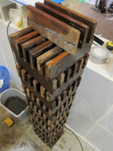
Myself and Roger have spent many an hour in gloves and masks working our way through the parquet and have got past the halfway point (~400 blocks). This is a picture of the blocks being dried after sponging off the sanding dust.
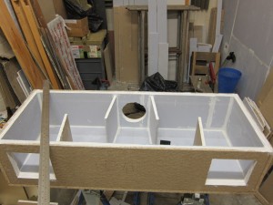
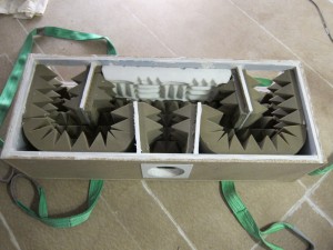
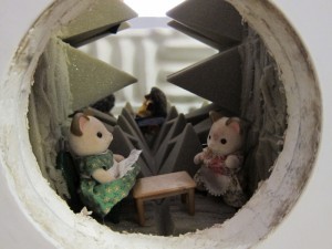
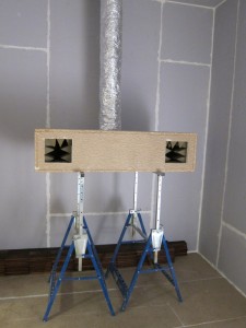
The air extraction fans have been plumbed into the exit box on the roof and I have dropped insulated ducting through the control room ceiling to test the custom silencer. It’s a simple chipboard box lined with acoustic plasterboard, which makes it a weighty bugger, to create a split with two direction changes to maximise absorption through reflecting the sound waves around as much as possible. The cross-sectional area also increases from inlet to exit (which is the opposite to the extracted air flow). The box was then lined with various acoustic foam materials I had lying around. As the box is split I could alternate linings to test which worked best. The final lining was then glued in place and quickly photographed with a variety of Sylvanian Family toy dioramas…because it seemed like a good idea…
Once the silencer was sealed up I managed to lift it onto some saw horses and plug in the ducting to check it performs as I planned. The result is a complete loss of the air rush and fan noise except for the lowest frequencies which are only audible if you put your ear to it. Considering the unit will be installed just below the ceiling that won’t be a temptation.
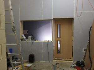
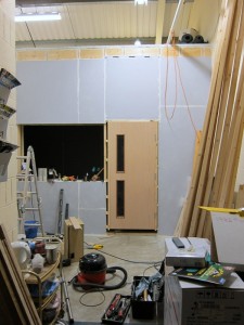
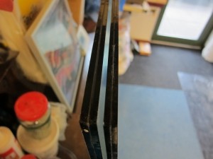
The control room doors have now been hung and are awaiting handles and sills. Though they are basic fire doors, they still weigh more than I’d like when fitting them. Now they’re on their ball bearing hinges they seem so light…bastards! They’ll still need to come off again before the final fit as seals need to go in yet.
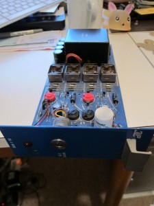
And finally…the distribution amplifiers I mentioned in the last post have been tested and despite the ‘not-exactly-hifi’ spec of the initial buffer IC (UA727) they sound great and at minimum gain punt out a respectable balanced line level, but the gain trim pot allows for another heft which I couldn’t measure as I was just testing it through my Fireface line inputs, which on the Lo-Gain (i.e. above +4dBu reference) setting clipped before the distribution amp even sweated. I think driving up to 10 metres of cable to the monitor mixers in the live room shouldn’t be a problem then! They sound great, or at least transparent, so headphone mixes will be nice and crisp. Lovely.

